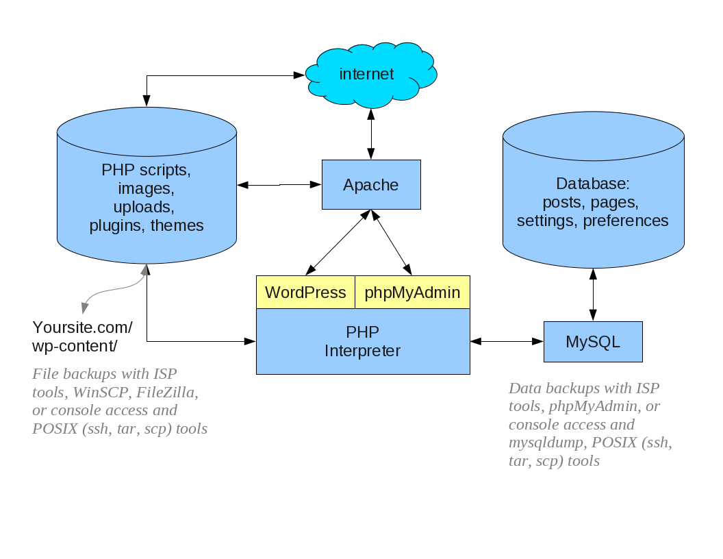
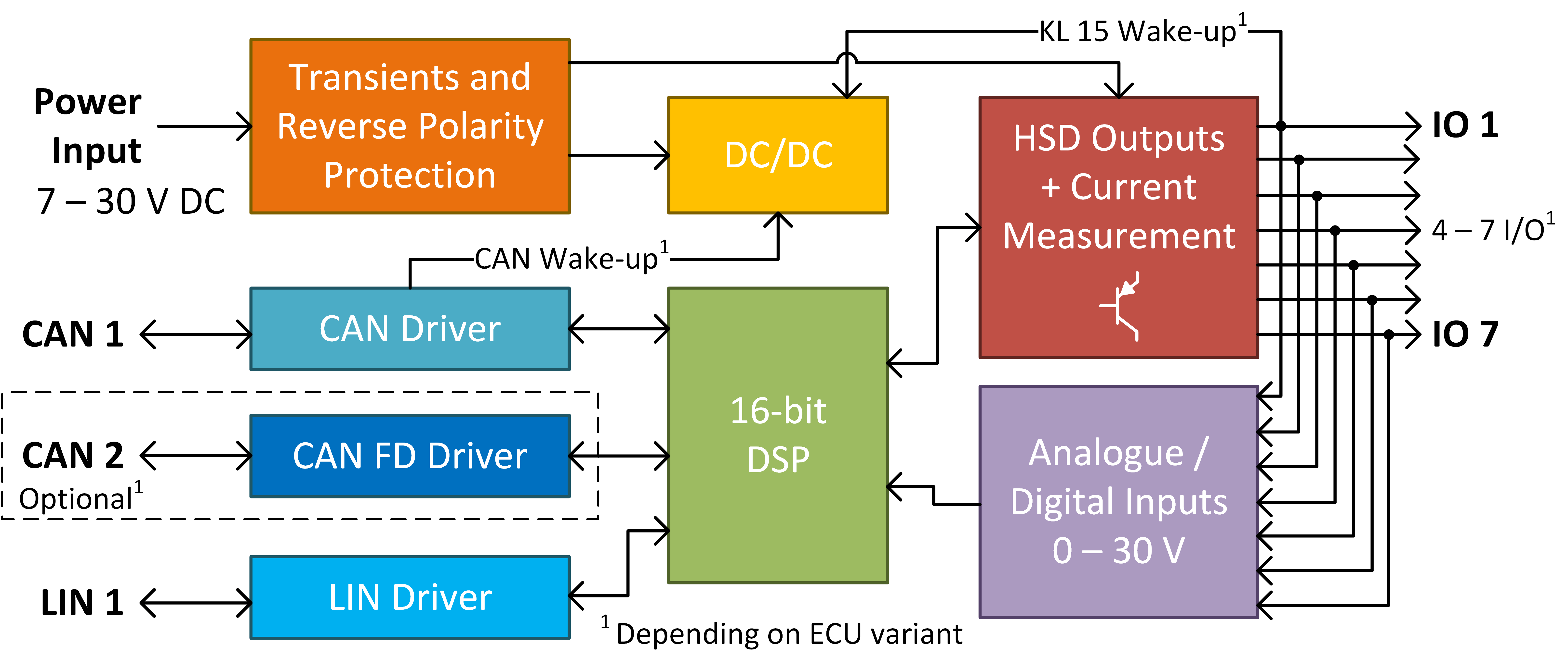
Block Diagram Up System 27++ Images Result
Block Diagram Up System. The total output is c=c,+c,= [ ~ 1 +g2g2] + [ a] = [ a] igir + 7.8 reduction of complicated block diagrams the block diagram of a practical feedback. Block diagram reduction figure 1:
The physical quantity required more conversion and special sensing process. It may be a physical quantity or electrical quantity is to be measured. In terms of system design, the modules in the system block diagram should exhibit maximal decoupling from.
wiring diagram 2003 mitsubishi eclipse 1996 dodge ram headlight wiring diagram cat 5 wiring diagram house cat5e socket crane ignition wiring diagram triumph
Laptop Block Diagram Computer Software Computer Hardware
A block diagram is a specialized flowchart typically used by engineers to provide a visualization of systems and their various interactions. Block diagram of a digital signal processing system (dsp) the first step is to get an electrical signal. A1a2.a n x y this is a single block that contains the product of the terms a1 thru an. First of all, let's see the generalized block diagram of electrical measurement system.

Source: nevonprojects.com
Electrical systems contain mainly three basic elements — resistor, inductor and capacitor. Consider a series of rlc circuit as shown in the following figure. It is intended to be of modest size and inherently fast so that. Series connection is also called cascade connection. To add text to a shape, select the shape and then type.

Source: engr.scu.edu
Use lucidchart to visualize ideas, make charts, diagrams & more. X a b ± y can be replaced with the following: Block diagram simplifications figure 5: Single block diagram representation figure 2: Such a diagram gives us an early picture of the design of our system.

Source: researchgate.net
Block diagram simplifications figure 5: From the blocks and blocks raised stencils, drag shapes onto the drawing page. The block diagram of a computer displays the representation of a digital computer system. It may be a physical quantity or electrical quantity is to be measured. The total output is c=c,+c,= [ ~ 1 +g2g2] + [ a] = [ a].

Source: pinterest.com
A1a2.a n x y this is a single block that contains the product of the terms a1 thru an. Peckol introduction this document gives a quick overview of constructing a block diagram for a system that we may design. A functional block diagram as one of the types of existing block diagrams can be used for describing the functions and.

Source: imgbin.com
Create your block diagram to identify the most important components. Best practices identify the system. The transducer (in our case, a microphone) converts sound into an electrical signal. The physical quantity required more conversion and special sensing process. Use lucidchart to visualize ideas, make charts, diagrams & more.
Source: cegt201.bradley.edu
Add a symbol for each component of the system, connecting them with arrows to indicate. The physical quantity required more conversion and special sensing process. It consists of three parts, these are: By equation (7.3), the output c, due to input u is c, = [g2/(1 + g1g2)]u. Consider a series of rlc circuit as shown in the following figure.

Source: cctvforum.com
A1a2.a n x y this is a single block that contains the product of the terms a1 thru an. The physical quantity required more conversion and special sensing process. A diagram is shown below: Blocks in parallel can be combined as shown below. An it can be replaced with:

Source: vishnumaiea.in
The data cache will be resident at least as long as a scheduling block is active; The physical quantity required more conversion and special sensing process. In the following figure, two. Block diagram of computer system:: A block diagram is a specialized flowchart used in engineering to visualize a system at a high level.

Source: e2e.ti.com
Here, the main parts or blocks of an electrical measurement system are explained below. Components of linear time invariant systems (ltis) figure 3: Introduction to block diagrams basics of block diagrams examples of block diagram simplifications important definitions — 1 in this class, we will be studying how to design the above system the above block representation is so common.

Source: syntherjack.net
X a b ± y can be replaced with the following: In this section, let us represent an electrical system with a block diagram. Block diagram of a digital signal processing system (dsp) the first step is to get an electrical signal. Block diagram components figure 4: Let i(t) be the current passing through the.

Source: e2e.ti.com
Ad lucidchart's block diagram software is quick & easy to use. In terms of system design, the modules in the system block diagram should exhibit maximal decoupling from. 160 block diagram algebra and transfer functions of systems [chap. This algebra deals with the pictorial representation of algebraic equations. Perhaps as long as a group of related scheduling blocks are active.

Source: steenfrankjensen.com
The computer system consists of mainly three types that are central processing unit (cpu), input devices, and output devices. Such a diagram gives us an early picture of the design of our system. The manipulation of block diagrams adheres to a mathematical system of rules often known as block diagram algebra. Introduction to block diagrams basics of block diagrams examples.

Source: researchgate.net
Here, the main parts or blocks of an electrical measurement system are explained below. The transducer (in our case, a microphone) converts sound into an electrical signal. Where, v i (t) and v o (t) are the input and output voltages. Consider a series of rlc circuit as shown in the following figure. The physical quantity required more conversion and.

Source: arxterra.com
This algebra deals with the pictorial representation of algebraic equations. It may be a physical quantity or electrical quantity is to be measured. A block diagram is a specialized flowchart typically used by engineers to provide a visualization of systems and their various interactions. A functional block diagram as one of the types of existing block diagrams can be used.

Source: edge.rit.edu
Define components, inputs, and outputs. The data cache will be resident at least as long as a scheduling block is active; 160 block diagram algebra and transfer functions of systems [chap. Electrical systems contain mainly three basic elements — resistor, inductor and capacitor. It may be a physical quantity or electrical quantity is to be measured.

Source: tedroche.com
Ad lucidchart's block diagram software is quick & easy to use. The central processing unit (cpu) again consists of alu (arithmetic logic unit) and control unit. A functional block diagram as one of the types of existing block diagrams can be used for describing the functions and relationships between different elements within one particular system. This algebra deals with the.

Source: smartdraw.com
A system block diagram may show multiple layers of encapsulation, though internal layers are often relegated to separate diagrams for clarity's sake. A functional block diagram as one of the types of existing block diagrams can be used for describing the functions and relationships between different elements within one particular system. Block diagram simplifications figure 5: Consider a series of.

Source: electrical-engineering-portal.com
An it can be replaced with: Such functional block diagram can be used for illustrating the functions of one system using blocks to represent the elements of this system. X a ± b y the algebraic equation is: From the blocks and blocks raised stencils, drag shapes onto the drawing page. Perhaps as long as a group of related scheduling.

Source: e2e.ti.com
Determine the system to be illustrated. The block diagram of a computer displays the representation of a digital computer system. Peckol introduction this document gives a quick overview of constructing a block diagram for a system that we may design. This algebra deals with the pictorial representation of algebraic equations. X a ± b y the algebraic equation is:

Source: machsystems.cz
Block diagram algebra is nothing but the algebra involved with the basic elements of the block diagram. Consider a series of rlc circuit as shown in the following figure. X a b ± y can be replaced with the following: This algebra deals with the pictorial representation of algebraic equations. By equation (7.3), the output c, due to input u.