Block Diagram Xor 12+ Images Result
Block Diagram Xor. Press save button to store the shots to your personal computer. Because of the properties of xor, one of the inputs can be used as a key for data going into the other input.
Chu, fpga prototyping by vhdl examples chapter 3.6, replicated structure 0+0+0 = 0 0+0+1 = 1 0+1+0 = 1 0+1+1 = 10. Di erential inverter vco, a xed divider and an xor phase detector.
1989 toyotum corolla engine diagram 2005 silverado factory stereo wiring 2001 pt cruiser starter wiring schematic duncan wiring diagram le paul
(a) Block diagram of TR gate, (b) Alloptical circuit of
1+0+0 = 1 1+0+1 = 10 1+1+0 = 10 1+1+1 = 11. Transistors q5 and q6 make the anding of inputs a and b, and transistor q7 supplies the oring of the nor output with the anded output. Let’s see an addition of single bits. Conclusion as this article demonstrates, fault tree diagrams and reliability block diagrams can be used to model and analyze similar types of logical configurations required for system reliability and related analyses.

Source: researchgate.net
Xor has two or more inputs and only one output. Chu, fpga prototyping by vhdl examples chapter 3.6, replicated structure 2.2.1 voltage controlled oscillator generates a digital clock. In this case, it is probably best to just create an empty block diagram in the current work space for the full adder, copy/paste the old design into it, and compile. A.

Source: untpikapps.com
So in calculators, computers and many digital applications use this gate. If it is not, you will need to add it manually. Xor has two or more inputs and only one output. A logic gate is a device that can perform one or all of the boolean logic operations and nand nor not or xnor and xor. Transistors q8, q9,.

Source: researchgate.net
But in terms of phase, it’s a linear block. Di erential inverter vco, a xed divider and an xor phase detector. If it is not, you will need to add it manually. 1+0+0 = 1 1+0+1 = 10 1+1+0 = 10 1+1+1 = 11. Add a new empty block diagram file called:

Source: researchgate.net
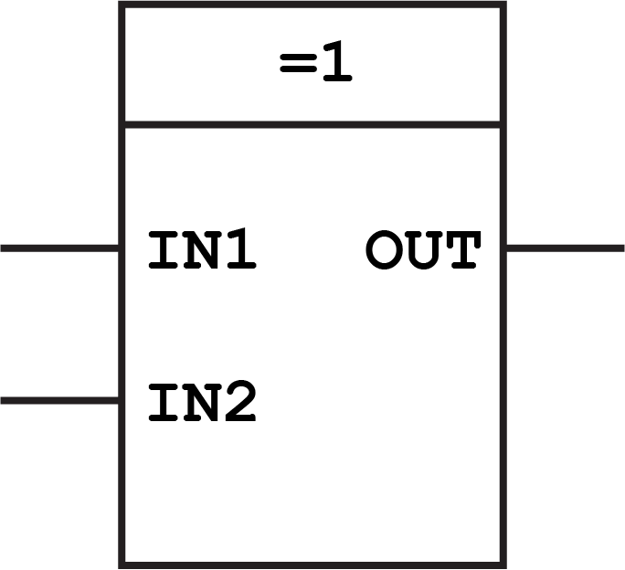
From this menu, at the top, highlight the open as item and from. Add a new empty block diagram file called: 0+0+0 = 0 0+0+1 = 1 0+1+0 = 1 0+1+1 = 10. Xor has two or more inputs and only one output. This video demonstrates the ladder diagram for xor gate.

Source: plcacademy.com
It produces output 1 for only those input combination that have odd number of 1’s. When the inputs are different, the xor ttit output input 1 input 2 xor logic output is true. Transistors q1, q2, q3, and q4 comprise the nor gate. In the above circuit, there are two half adder circuits that are combined using the or gate..
![52 in terms of XORXNOR and MUX [3] Download Scientific 52 in terms of XORXNOR and MUX [3] Download Scientific](https://i2.wp.com/www.researchgate.net/profile/Ranjan-Senapati/publication/328190630/figure/download/fig4/AS:680080435060737@1539155219238/52-in-terms-of-XOR-XNOR-and-MUX-3.png)
Source: researchgate.net
Let’s see an addition of single bits. Function block diagrams (fbds) 3 structured text (st) instruction list (il) sequential function charts (sfcs). If both are 0 or both are 1, then the x\൏r gate will output a 0 also. In boolean notation yabarbbbara figures 1 and 2 show two logic block diagrams to realize this function. Xor is an exclusive.

Source: crypto.stackexchange.com
Given below is two input truth table for xor gate. A xor gate is a gate that is 1 only when one and only one of the two inputs is also 1. So in calculators, computers and many digital applications use this gate. Both devices are layed out together on a 1.5x1.5mm die. The augent and addent bits are the.

Source: researchgate.net
Xor is an exclusive logic gate. In the above circuit, there are two half adder circuits that are combined using the or gate. Let’s see an addition of single bits. Transistors q5 and q6 make the anding of inputs a and b, and transistor q7 supplies the oring of the nor output with the anded output. For n input edges,.

Source: martinguitard15ideas.blogspot.com
For n input edges, only one output edge occurs. Xor phase detector ref div xor xor. Di erential inverter vco, a xed divider and an xor phase detector. Conclusion as this article demonstrates, fault tree diagrams and reliability block diagrams can be used to model and analyze similar types of logical configurations required for system reliability and related analyses. Let’s.

Source: slideserve.com
The augent and addent bits are the input states, and carry and sum are the output states of the half adder. If both are 0 or both are 1, then the x\൏r gate will output a 0 also. 2.2.1 voltage controlled oscillator generates a digital clock. If it is not, you will need to add it manually. A half adder.

Source: researchgate.net
0+0+0 = 0 0+0+1 = 1 0+1+0 = 1 0+1+1 = 10. Conclusion as this article demonstrates, fault tree diagrams and reliability block diagrams can be used to model and analyze similar types of logical configurations required for system reliability and related analyses. A half adder is a type of combinational arithmetic circuitry that uses two numbers addition and outputs.

Source: researchgate.net
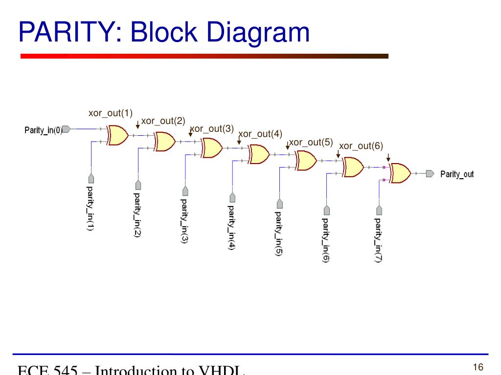
A logic block diagram for the xor circuit. Di erential inverter vco, a xed divider and an xor phase detector. Xor has two or more inputs and only one output. In the above circuit, there are two half adder circuits that are combined using the or gate. A logic gate is a device that can perform one or all of.

Source: researchgate.net
If it is not, you will need to add it manually. Another logic block diagram for the xor gate. Transistors q1, q2, q3, and q4 comprise the nor gate. But in terms of phase, it’s a linear block. A half adder is a type of combinational arithmetic circuitry that uses two numbers addition and outputs an s, sum bit, as.

Source: mouser.co.za
If it is not, you will need to add it manually. Di erential inverter vco, a xed divider and an xor phase detector. Thus, the equations can be written as 0+0+0 = 0 0+0+1 = 1 0+1+0 = 1 0+1+1 = 10. Xor phase detector ref div xor xor.

Source: researchgate.net
But in terms of phase, it’s a linear block. When the inputs are different, the xor ttit output input 1 input 2 xor logic output is true. 2.2.1 voltage controlled oscillator generates a digital clock. As we know that, the. A logic block diagram for the xor gate.

Source: pinterest.co.kr
Because of the properties of xor, one of the inputs can be used as a key for data going into the other input. As we know that, the. From this menu, at the top, highlight the open as item and from. If both are 0 or both are 1, then the x\൏r gate will output a 0 also. Transistors q8,.

Source: w-ramach-schematu.blogspot.com
In this case, it is probably best to just create an empty block diagram in the current work space for the full adder, copy/paste the old design into it, and compile. Press save button to store the shots to your personal computer. 1+0+0 = 1 1+0+1 = 10 1+1+0 = 10 1+1+1 = 11. Xor phase detector ref div xor.

Source: electroniclinic.com
1 full adder block diagram. This diagram shows how the xor function works. Given below is two input truth table for xor gate. A half adder is a type of combinational arithmetic circuitry that uses two numbers addition and outputs an s, sum bit, as well as a c, carry but. 2.2.1 voltage controlled oscillator generates a digital clock.

Source: wiringdiagramall.blogspot.com
Conclusion as this article demonstrates, fault tree diagrams and reliability block diagrams can be used to model and analyze similar types of logical configurations required for system reliability and related analyses. This video demonstrates the ladder diagram for xor gate. Function block diagrams (fbds) 3 structured text (st) instruction list (il) sequential function charts (sfcs). When the inputs are different,.

Source: researchgate.net
In this case, it is probably best to just create an empty block diagram in the current work space for the full adder, copy/paste the old design into it, and compile. Transistors q1, q2, q3, and q4 comprise the nor gate. 1) xor x ⊕ y = xy’ + x’y 11 x y. Let’s see an addition of single bits..