Circuit Diagram Java 48+ Images Result
Circuit Diagram Java. To turn a switch on or off, just click on it. For control signal s 1 = 0, s 0 = 0, the output is.
In this blog post, we implement a custom simulator that generates a quantum circuit diagram in the q|pic format from q# program execution traces. It’s used by bpmn.io (the creators of this library) as a building block for a number of other libraries by the same company for specifying business process models, decision models, and case plan models. So 2e and 4.7e are labels for a resistor on a schematic (i missed read that part) per the koa page above, 2e is a size indicator 1210 (inch code) or 3.2 mm by 2.6 mm.
48 chevy engine internal diagram cat5e wiring diagram router switch xj fuse box layout power door lock wiring diagram toyotum lh113
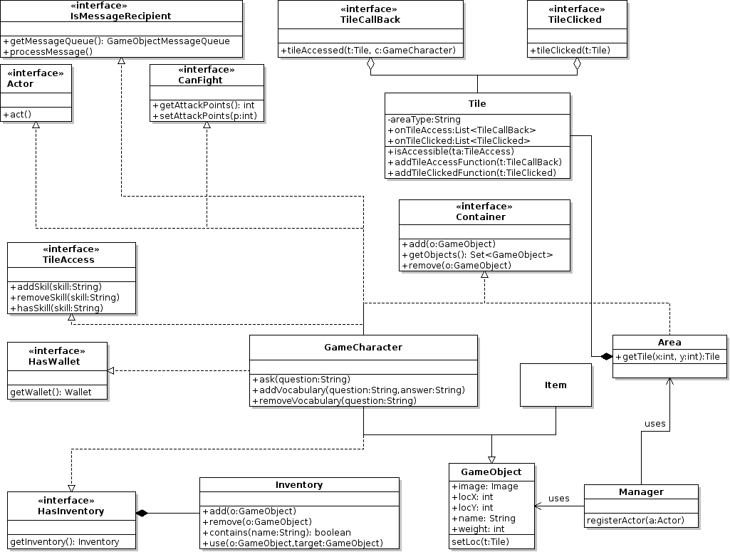
Uml Diagram Java Data Diagram Medis
Must contain at least 4 different symbols;answer to lab 9: For control signal s 1 = 0, s 0 = 0, the output is. The gray color indicates ground. We show how the simulator can be integrated into a q# test project to selectively create.

Source: robhosking.com
A ttl circuit can support at most 10 gates at its output. You can change the numbers of the relay to operate various home appliances accordingly. A red color indicates negative voltage. This project hosts the source code and technical documents of those devices. The moving yellow dots indicate current.
![[DO_4947] Circuit Diagram Maker Java Wiring Diagram [DO_4947] Circuit Diagram Maker Java Wiring Diagram](https://i2.wp.com/static-cdn.imageservice.cloud/555488/how-to-generate-sequence-diagram-from-java.png)
Source: cular.phon.renstra.fr09.org
A ttl circuit can support at most 10 gates at its output. 6 to 30 characters long; You need to select a diagram to visualize the interaction. The above block diagram describes the construction of the full adder circuit. The features and the objectives of the circuit editor will be described and also short description about the

Source: youtube.com
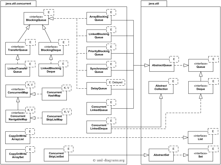
As you know, every logic circuit is an object diagram, which means it has a metamodel with constraints that verifies that circuits, such as the above, are sane.your assignment is to incrementally develop a java program that allows you to: Diagram.js core library for creating and displaying diagrams. 6 to 30 characters long; The moving yellow dots indicate current. The.

Source: skippingtheinbetween.blogspot.com
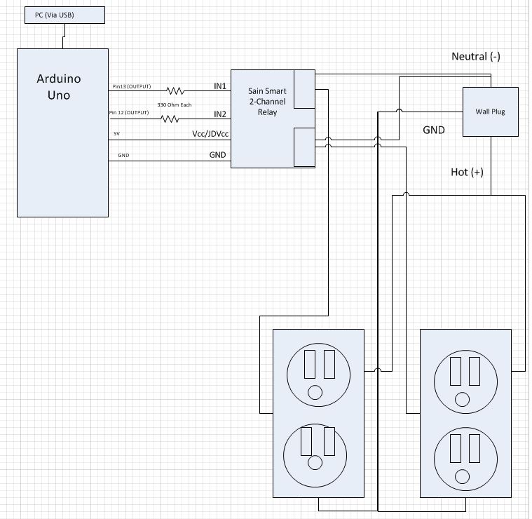
Cpu what does that mean ? We have used four relays for four appliances. This is an electronic circuit simulator. As the name suggests, this software is capable of providing an environment to design new circuit with different circuit components. Circuit diagram, firmware source code and romaji table for physical input devices for google japanese input announced on april 1st.these.
Source: diagramblog.blogspot.com
6 to 30 characters long; It’s used by bpmn.io (the creators of this library) as a building block for a number of other libraries by the same company for specifying business process models, decision models, and case plan models. A circuit diagram is a visual display of an electrical circuit using either basic images of parts or industry standard symbols..

Source: kovodym.blogspot.com
The above block diagram describes the construction of the full adder circuit. The moving yellow dots indicate current. The circuit is designed using arduino, bluetooth, relay, and leds. Select src > registercontroller.java > register (string,int). In the above circuit, there are two half adder circuits that are combined using the or gate.

Source: electronics.stackexchange.com
Draw.io can import.vsdx, gliffy™ and lucidchart™ files. Diagrams.net (formerly draw.io) is free online diagram software. A red color indicates negative voltage. Sets in the java collection framework for this week's lab, you will use We have connected the bluetooth serially with the arduino.

Source: codedump.io
The 'sum' output of the first adder. Design circuits online in your browser or using the desktop application. Plantuml is a component that allows to quickly write. This project hosts the source code and technical documents of those devices. Diagram.js core library for creating and displaying diagrams.

Source: medium.com
For control signal s 1 = 0, s 0 = 0, the output is. Select src > registercontroller.java > register (string,int). The average propagation delay for a ttl circuit is about 9ns. The features and the objectives of the circuit editor will be described and also short description about the Draw.io can import.vsdx, gliffy™ and lucidchart™ files.

Source: skippingtheinbetween.blogspot.com
Half wave rectifier is a diode circuit which is used to transform alternating voltage (ac supply) to direct voltage (dc supply).a single diode is used in the hwr circuit for the transformation of ac to dc. The average propagation delay for a ttl circuit is about 9ns. Circuit diagram is a free application for making electronic circuit diagrams and exporting.

Source: stackoverflow.com
Diagrams.net (formerly draw.io) is free online diagram software. Circuit diagram, firmware source code and romaji table for physical input devices for google japanese input announced on april 1st.these devices showed in the videos are actually connected to a pc via usb. When the applet starts up you will see an animated schematic of a simple lrc circuit. The circuit is.

Source: javacircuit.blogspot.com
A red color indicates negative voltage. The gray color indicates ground. Diagram.js core library for creating and displaying diagrams. We have used four relays for four appliances. You need to select a diagram to visualize the interaction.

Source: youtube.com
It’s used by bpmn.io (the creators of this library) as a building block for a number of other libraries by the same company for specifying business process models, decision models, and case plan models. As a result, a uml sequence diagram is. Sets in the java collection framework for this week's lab, you will use A ttl circuit can support.
Source: javaroidinterview.blogspot.com
The circuit functionality of a 1 bit alu is shown here, depending upon the control signal s 1 and s 0 the circuit operates as follows: The relay is used to operate the home appliances. In this blog post, we implement a custom simulator that generates a quantum circuit diagram in the q|pic format from q# program execution traces. The.

Source: diagramwiringexplained.blogspot.com
The circuit functionality of a 1 bit alu is shown here, depending upon the control signal s 1 and s 0 the circuit operates as follows: It’s used by bpmn.io (the creators of this library) as a building block for a number of other libraries by the same company for specifying business process models, decision models, and case plan models..

Source: galvinconanstuart.blogspot.com
A circuit diagram is a visual display of an electrical circuit using either basic images of parts or industry standard symbols. As a result, a uml sequence diagram is. Diagram.js core library for creating and displaying diagrams. Design circuits online in your browser or using the desktop application. We have used four relays for four appliances.

Source: robhosking.com
Plantuml is a component that allows to quickly write. As a result, a uml sequence diagram is. Select src > registercontroller.java > register (string,int). The gray color indicates ground. Node voltage method description & circuit analysis sample mesh current method description & circuit analysis sample alternating currents circuits alternating current (ac), voltage, sinusoidal waveform frequency, period, phase angle of sinusoidal.

Source: diagramedia.blogspot.com
For control signal s 1 = 0, s 0 = 0, the output is. This project hosts the source code and technical documents of those devices. We show how the simulator can be integrated into a q# test project to selectively create. Flowchart maker and online diagram software. The create new sequence diagram option is selected and diagram name is.

Source: youtube.com
A ttl circuit can support at most 10 gates at its output. This is an electronic circuit simulator. In this blog post, we implement a custom simulator that generates a quantum circuit diagram in the q|pic format from q# program execution traces. We have connected the bluetooth serially with the arduino. The electronic circuit diagram refers to the circuit diagram.

Source: datadiagram.blogspot.com
Sets in the java collection framework for this week's lab, you will use The circuit is designed using arduino, bluetooth, relay, and leds. As a result, a uml sequence diagram is. Half wave rectifier is a diode circuit which is used to transform alternating voltage (ac supply) to direct voltage (dc supply).a single diode is used in the hwr circuit.