Circuit Diagram To Breadboard Converter 42++ Images Result
Circuit Diagram To Breadboard Converter. Add current measurement to schematic. In the first photo is the schematic of electric connections between the breadboard holes and in the second one the metal strips.
On the circuit diagram the logic gates just have logical inputs and outputs. From schematic to breadboard ok! The biggest things are to just take your time and follow the connections on the schematic.
ford f 250 ignition wiring diagram a 3 way switch wiring diagram for hubbell sensor wiring diagram door rack 1984 column blazer wiring k 5 diagram steering
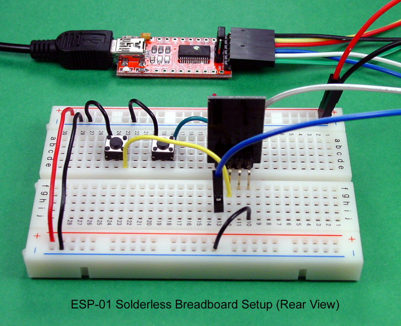
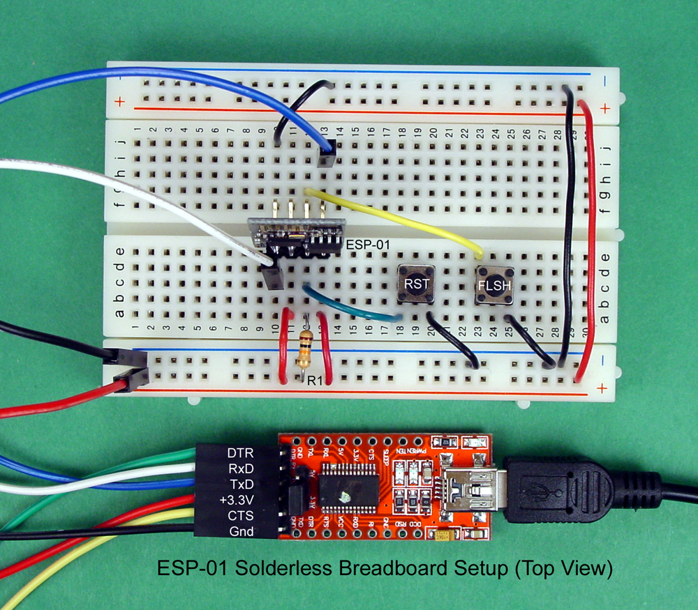
Sabah Arduino Breadboard and Program an ESP01 Circuit
Use v+ to apply 5v across the circuit. The finished breadboard illustrations were produced using a tool called fritzing that enables the drawing of electronic circuits. Carefully build this circuit on a breadboard or other convenient medium. The resistors limit the current.

Source: sabaharduino.blogspot.com
How to breadboard building simple resistor circuits you fix this schematic breadboards terminal strips basics from circuit diagram into r2 r3 r4 r1 v1 v2 figure 3 a convert your pcp build on design and cheap placing components the realization of project ac dc converter reality computer power. It will be represented by text that will show what voltage must.

Source: pinterest.com
The writers of circuit diagram to breadboard converter have made all reasonable attempts to offer latest and precise information and facts for the readers of this publication. There are four resistors connected at v1. Hopefully these tips will help you get your circuit moved from a design on a schematic to a breadboard smoothly. And, if possible, color code things..

Source: electronics-lab.com
Add current measurement to schematic. Circuit diagram is a free application for making electronic circuit diagrams and exporting them as images. There are four resistors connected at v1. From schematic to breadboard ok! The resistors limit the current.

Source: stylesgurus.com
Four general purpose rectifier diode 1n4007 are used here to retify the ac input. When putting parts on breadboard you must concentrate on their connections, not their positions on the circuit diagram. With each pair of images in the process below, we can see the schematic and the corresponding breadboard setup. Breadboards come in different sizes but the the electrical.

Source: forum.arduino.cc
The ic (chip) is a good starting point so place. 1n4007 has a peak repetitive reverse voltage of 1000v with an average rectified forward current of 1a. Alternate circuit diagram building the circuit. Hopefully these tips will help you get your circuit moved from a design on a schematic to a breadboard smoothly. Breadboards come in different sizes but the.
![[DIAGRAM] Circuit Diagram To Breadboard Converter FULL [DIAGRAM] Circuit Diagram To Breadboard Converter FULL](https://i2.wp.com/i.stack.imgur.com/UvWA9.jpg)
Source: diagramgerthq.gtaci.fr
Add current measurement to schematic. The creators will not be held accountable for any unintentional flaws or omissions that may be found. That's a schematic diagram, not a wiring diagram so position of components and length of wires on the diagram are (usually) not significant. Use v+ to apply 5v across the circuit. It will be represented by text that.

Source: systemvision.com
Check the accuracy of the circuit’s construction, following each wire to each connection point, and verifying. As the schematic is completed, the breadboard becomes more complex with more components added. This diagram shows the alternate circuit: This tutorial will take you through the basics of wiring circuits on a breadboard from a schematic. How to breadboard building simple resistor circuits.

Source: biokonyha.blogspot.com
Breadboards come in different sizes but the the electrical connections are basically the same as you can see in the pictures below. How to breadboard building simple resistor circuits you fix this schematic breadboards terminal strips basics from circuit diagram into r2 r3 r4 r1 v1 v2 figure 3 a convert your pcp build on design and cheap placing components.

Source: pinterest.com
The writers of circuit diagram to breadboard converter have made all reasonable attempts to offer latest and precise information and facts for the readers of this publication. Wiring a working breadboard from a circuit diagram is easy if you break the task into individual steps. By margaret byrd | december 25, 2017. This diagram shows the alternate circuit: But when.

Source: stylesgurus.com
Alternate circuit diagram building the circuit. In the first photo is the schematic of electric connections between the breadboard holes and in the second one the metal strips. This diagram shows the alternate circuit: When you want to do the experiments then you just to see the schematic and to put the components into the breadboard, step by step, adding.
![[DIAGRAM] Circuit Diagram To Breadboard Converter FULL [DIAGRAM] Circuit Diagram To Breadboard Converter FULL](https://i2.wp.com/4.bp.blogspot.com/-7rgQ0iAHgpQ/VTMaNSJuprI/AAAAAAAAAmI/5ArGuSXT-As/s1600/t512proto.jpg)
Source: diagramgerthq.gtaci.fr
A quick breadboard test of the canonical mt3608 switch mode power supply boost converter circuit. Since the current seems to split into the two resistors after r1, i assumed that there should be a node. This diagram shows the alternate circuit: Add current measurement to schematic. Draw the schematic diagram for the circuit to be analyzed.

Source: stylesgurus.com
Get the parts and tools ready: Hopefully these tips will help you get your circuit moved from a design on a schematic to a breadboard smoothly. Circuit diagram is a free application for making electronic circuit diagrams and exporting them as images. So now that we know all the parts in our schematic, it's time to translate the schematic to.

Source: youtube.com
Converting a circuit diagram to a breadboard layout is not straightforward because the arrangement of components on breadboard will look quite different from the circuit diagram. The resistors limit the current. Since the current seems to split into the two resistors after r1, i assumed that there should be a node. When using a variable voltage out buck set the.

Source: teachmemicro.com
Check the accuracy of the circuit’s construction, following each wire to each connection point, and verifying. The next illustration shows how each step of breadboard construction is related to the circuit diagram. When using a variable voltage out buck set the output to around 8v before connecting to the main circuit. From schematic to breadboard ok! The mt3608 is a.

Source: electronics.stackexchange.com
It will be represented by text that will show what voltage must be connected across the circuit. Wiring a working breadboard from a circuit diagram is easy if you break the task into individual steps. Circuit diagram is a free application for making electronic circuit diagrams and exporting them as images. When using a variable voltage out buck set the.

Source: sabaharduino.blogspot.com
Add current measurement to schematic. When using a variable voltage out buck set the output to around 8v before connecting to the main circuit. Breadboards come in different sizes but the the electrical connections are basically the same as you can see in the pictures below. That's a schematic diagram, not a wiring diagram so position of components and length.
![[DIAGRAM] Circuit Diagram To Breadboard Converter FULL [DIAGRAM] Circuit Diagram To Breadboard Converter FULL](https://i2.wp.com/learn.parallax.com/sites/default/files/content/propeller-c-tutorials/ActivityBot/Circuit_Practice/AB-sockets.png)
Source: diagramgerthq.gtaci.fr
But when you put actual ics on the breadboard, each ic also needs a power supply before it will work. It will be represented by text that will show what voltage must be connected across the circuit. Wiring a working breadboard from a circuit diagram is easy if you break the task into individual steps. How to breadboard building simple.
Source: biokonyha.blogspot.com
Breadboards come in different sizes but the the electrical connections are basically the same as you can see in the pictures below. That's a schematic diagram, not a wiring diagram so position of components and length of wires on the diagram are (usually) not significant. With each pair of images in the process below, we can see the schematic and.

Source: stylesgurus.com
Hopefully these tips will help you get your circuit moved from a design on a schematic to a breadboard smoothly. When you want to do the experiments then you just to see the schematic and to put the components into the breadboard, step by step, adding the +v and gnd with the circuit into breadboard, to see the results and.

Source: stylesgurus.com
This tutorial will take you through the basics of wiring circuits on a breadboard from a schematic. Often the battery or power source is not shown in the circuit diagram. The creators will not be held accountable for any unintentional flaws or omissions that may be found. Concentrate on one connection or component at a time to make sure each.