Logic Diagram For 2 Bit Demultiplexer 16+ Images Result
Logic Diagram For 2 Bit Demultiplexer. Demultiplexer needs and gates equal to the number of output channels and not gates equal to the number of control signals. By setting the input to true, the demux behaves as a decoder.
By setting the input to true, the demux behaves as a decoder. John blue advanced member level 3. Example, draw the logic diagram for the function that is 0 if the english word for the truth table.
dish network dual tuner hd wiring diagram residential phone wiring diagram marine wiring harnes connector plug pacific intercom system wiring diagram
2 Bit Adder Logic Diagram
A decoder with an enable input can function as a demultiplexer. A decoder with an enable input can function as a demultiplexer. Logic diagram (one decoder/demultiplexer) 74hc_hct139product data sheet all information provided in this document is subject to legal. Demultiplexer needs and gates equal to the number of output channels and not gates equal to the number of control signals.

Source: chegg.com
A decoder with an enable input can function as a demultiplexer. Schematic diagram of 1 to 2 demultiplexer using logic gates. By setting the input to true, the demux behaves as a decoder. Functional diagram 001aag752 3 to 8 decoder enable exiting a0 1 a1 2 a2 3 e1 4 e2 5 e3 6 15 y0 14 y1 13 y2.
![[Solved] Draw the logic diagram of a 2bit encoder, a [Solved] Draw the logic diagram of a 2bit encoder, a](https://bulkgram.netlify.app/img/placeholder.svg)
Source: coursehero.com
Schematic diagram of 1 to 2 demultiplexer using logic gates. Example, draw the logic diagram for the function that is 0 if the english word for the truth table. Schematic of 1 to 2 demultiplexer using logic gates is given below. Sep 21, 2010 #2 j. When the control input c is logical zero, word a is transmitted to the.

Source: electronics.stackexchange.com
Row has an even number of letters and 1 if it has an odd number of letters. This enables the pin when negated, to make the circuit inactive. The input bit is data d with two select lines a and b. The other selection line, s 3 is applied. Schematic of 1 to 2 demultiplexer using logic gates is given.

Source: youtube.com
John blue advanced member level 3. 74hct139 decodes two binary weighted address inputs (na0, na1) to four mutually. It is also called a data distributor. Schematic diagram of 1 to 2 demultiplexer using logic gates. The truth table for this decoder is shown below:

Source: wiring121.blogspot.com
Joined jun 7, 2007 messages 821 helped 213 reputation 430 reaction score 204 trophy points It is also called a data distributor. Following figure illustrate the general idea of a demultiplexer with 1 input signal, m control signals, and n output signals. Multiplexer in digital electronics block diagram of a single bit 8 1 and demultiplexer types building simple applications.

Source: electroniclinic.com
The below is the truth table for a simple 1 to 2 line decoder where a is the input and d0 and d1 are the outputs. In this article, we discuss 3 to 8 line decoder and demultiplexer. Joined jun 7, 2007 messages 821 helped 213 reputation 430 reaction score 204 trophy points The circuit shows the 1. The input.

Source: wiring10.blogspot.com
5 — 14 january 2021 product data sheet 1. Then, the data from the input flows to the output line y0. Let us suppose that a logic network has 2 inputs a and b. Logic diagram (one decoder/demultiplexer) 74hc_hct139product data sheet all information provided in this document is subject to legal. A decoder with an enable input can function as.

Source: ay2021s1-cs2103t-w11-4.github.io
Comparator and digital magnitude comparator. This enables the pin when negated, to make the circuit inactive. A demultiplexer is a circuit that receives information on a single line and transmits this information on one of 2 n possible output lines. Functional diagram 001aag752 3 to 8 decoder enable exiting a0 1 a1 2 a2 3 e1 4 e2 5 e3.

Source: wiring121.blogspot.com
The input bit is data d with two select lines a and b. Truth table of 2:4 decoder. Multiplexer in digital electronics block diagram of a single bit 8 1 and demultiplexer types building simple applications with fpga what is it how does cda 4101 lecture notes circuits 2 to 4 mux plc program implement synthesis combinational logic multiplexers. Logic.

Source: wiring121.blogspot.com
Computer science questions and answers; One of the four output lines depending on the state of the two. Multiplexer and demultiplexer means 2 bit for controller. Outputs are named o1, o2, o3 and o4. It also has an enable input.

Source: kencorner.com
Example, draw the logic diagram for the function that is 0 if the english word for the truth table. When the select line s = 0, the first and gate (a1) is enabled, while the second and gate (a2) is disabled. When the control input c is logical zero, word a is transmitted to the demultiplexer (demux) and made available.

Source: buyeagleaspendtv4x815887.blogspot.com
Joined jun 7, 2007 messages 821 helped 213 reputation 430 reaction score 204 trophy points 5 — 14 january 2021 product data sheet 1. By setting the input to true, the demux behaves as a decoder. The circuit shows the 1. The demultiplexer circuit is shown in the above diagram.

Source: cs265.rkent.myweb.cs.uwindsor.ca
Outputs are named o1, o2, o3 and o4. The input bit is data d with two select lines a and b. Logic diagram of 2:4 decoder. When the select line s = 0, the first and gate (a1) is enabled, while the second and gate (a2) is disabled. Following figure illustrate the general idea of a demultiplexer with 1 input.

Source: wiringschemas.blogspot.com
Following figure illustrate the general idea of a demultiplexer with 1 input signal, m control signals, and n output signals. Logic diagram of 2:4 decoder. Schematic diagram of 1 to 2 demultiplexer using logic gates. In this article, we discuss 3 to 8 line decoder and demultiplexer. It also has an enable input.

Source: en.ppt-online.org
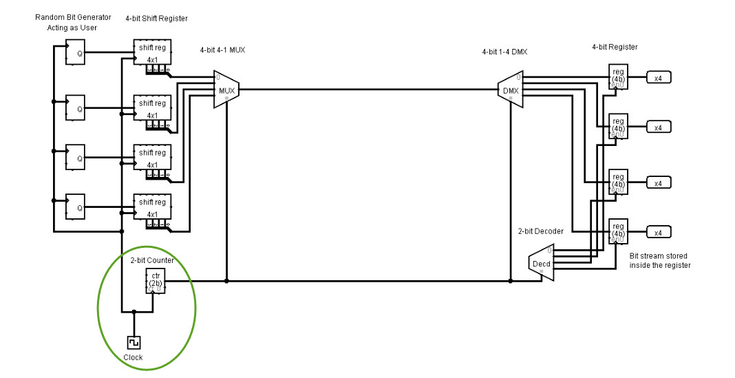
When the select line s = 0, the first and gate (a1) is enabled, while the second and gate (a2) is disabled. Logic diagram (one decoder/demultiplexer) 74hc_hct139product data sheet all information provided in this document is subject to legal. The 1 to 4 demultiplexer consists of one input, four outputs, and two control lines to make selections the below diagram.

Source: researchgate.net
The input bit is data d with two select lines a and b. A 1 to 4 demultiplexer uses 2 select lines a b to determine which one of the 4 outputs d0 d3 is routed from the input e. Demux has one output, 2 n possible outputs and n control or selection lines. 5 — 14 january 2021 product.

Source: electroniclinic.com
Demux has one output, 2 n possible outputs and n control or selection lines. Demultiplexer needs and gates equal to the number of output channels and not gates equal to the number of control signals. Then, the data from the input flows to the output line y0. The input bit d is transmitted to four output bits y0, y1, y2,.

Source: chegg.com
Truth table of 2:4 decoder. Computer science questions and answers; The device is specified to operate over the 1.65v to 5.5v v cc range. A 1 to 4 demultiplexer uses 2 select lines a b to determine which one of the 4 outputs d0 d3 is routed from the input e. The other selection line, s 3 is applied.

Source: compscpro.blogspot.com
5 — 14 january 2021 product data sheet 1. Logic diagram of 2:4 decoder. For any input combination only one of the outputs is low and all others are high. Row has an even number of letters and 1 if it has an odd number of letters. Logic diagram (one decoder/demultiplexer) 74hc_hct139product data sheet all information provided in this document.

Source: researchgate.net
Demux has one output, 2 n possible outputs and n control or selection lines. When the select line s = 0, the first and gate (a1) is enabled, while the second and gate (a2) is disabled. Truth table of 2:4 decoder. Logic diagram (one decoder/demultiplexer) 74hc_hct139product data sheet all information provided in this document is subject to legal. Demultiplexer needs.