Potentiometer Motor Control Wiring Diagram 11++ Images Result
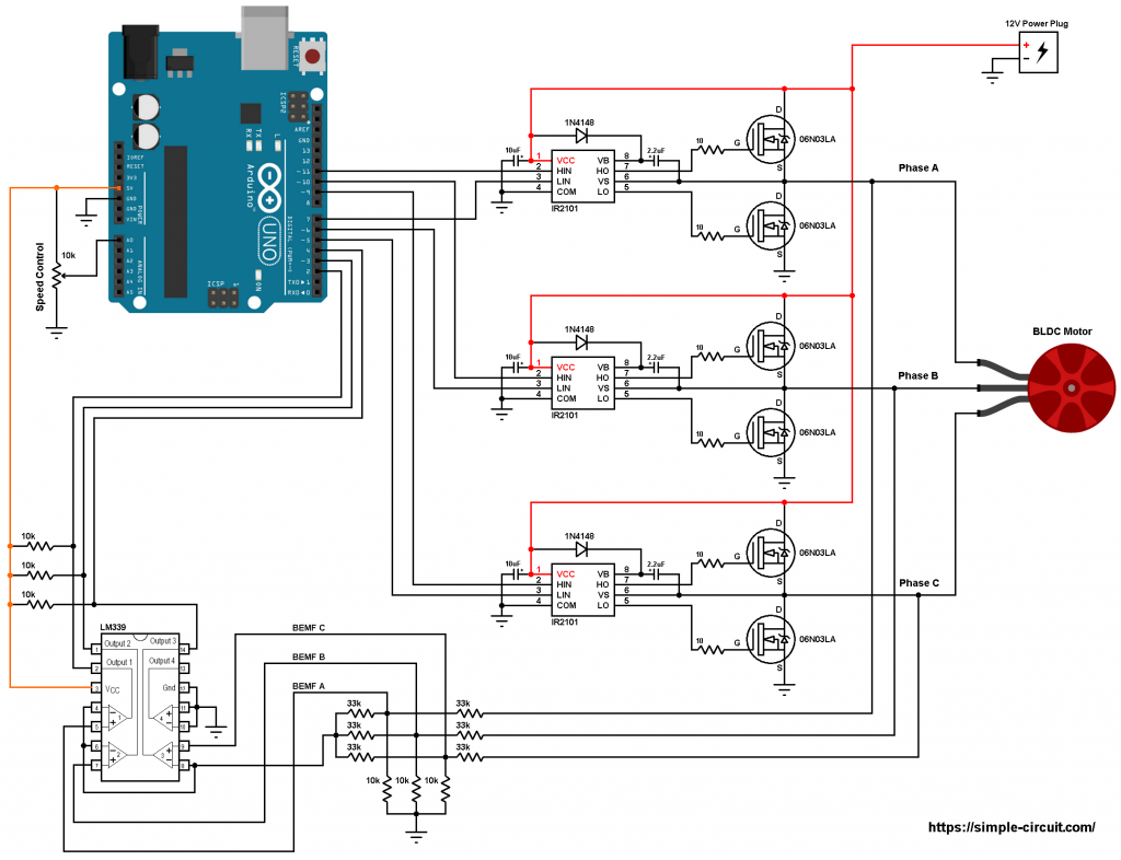
Potentiometer Motor Control Wiring Diagram. Connect the circuit as shown in figure i. Connect the esp32 board to your pc via a micro usb cable.
Energize motor and check for proper rotation. How to wire a potentiometer. If your potentiometer has a high resistance (as measured between the two outer terminals), the motor might not move at all until the wiper is.
1974 ford f100 460 engine diagram fuel filter cartridge 2005 ford super duty fuse diagram g8 gt wheel sensor wiring diagram
Potentiometer Wiring Diagram Cadician's Blog
The above image shows a simple circuit to dim an led. Control a servo motor with a potentiometer and arduino wiring diagram for controlling a servo motor with a potentiometer and arduino. The middle pin and one of the side pins. Potentiometer on the go principle diagram.

Source: circuitdigest.com
The ground is generally off, terminal 2 is the main switch, and the third terminal is the variable switch that can be turned. C to throttle position potentiometer top of firewall 48 volt dc motor control & terminal block wiring dc motor control j. Potentiometer diagram the potentiometer has two symbols, one of them is considered as its international standard.

Source: allaboutcircuits.com
Servo motor with arduino uno and potentiometer wiring diagram schematic circuit arduino arduino shield analog to digital converter. Wiring illustration for using a potentiometer as a rheostat. It is a three terminal device with a schematic symbol similar to that of a resistor. Atv12h075m2 main range of product altivar 12. V set the motor parameters in conf mode only.

Source: invent.module143.com
Wikihow.com) you can suppose a potentiometer as a dimmer instrument. Wiring these potentiometers (also known as pots for short) is fairly straightforward if you follow this diagram. Switch • integral spring return returns motor to normal position in the event of power. Pt2399 reverb circuit — switch and potentiometer wiring. Single phase power supply wiring diagram a1 drive km1 contactor.

Source: homemade-circuits.com
The circuit is designed to give control signals to the servoic1 is designed as an astable multi vibrator which can give pulses for the operation of the servo. Controlling the position of a servo motor with a potentiometer is very easy and can be very useful if you want to adjust the motor position by hand. The voltage supply is.

Source: youtube.com
Potentiometers located in the wiring compartment. Troubleshooting mounted speed control dial 1. C to throttle position potentiometer top of firewall 48 volt dc motor control & terminal block wiring dc motor control j. A potentiometer is usually used to control an input signal so that it can be regulated. Connect the circuit as shown in figure i.

Source: arduinogetstarted.com
To use external speed control turn integral potentiometer fully clockwise (100%). Use of voltmeter over ammeter to verify a continuous circuit. It is a three terminal device with a schematic symbol similar to that of a resistor. Pt2399 reverb circuit — switch and potentiometer wiring. The voltage supply is connected across terminals 1 and 3, positive lead to terminal one.

Source: roboticelectronics.in
As you can see in the wiring diagram above, the servo motor is. The iec standard symbol for the potentiometer is a rectangle between two straight lines and the ansi standard potentiometer symbol contains two straight. Potentiometer diagram the potentiometer has two symbols, one of them is considered as its international standard symbol and the other one is the american.

Source: facybulka.me
Controlling the position of a servo motor with a potentiometer is very easy and can be very useful if you want to adjust the motor position by hand. The terminal 2 is connected to the wiper. Open arduino ide on your pc. As you can see in the wiring diagram above, the servo motor is. How to wire a potentiometer.

Source: simple-circuit.com
Learn how to use potentiometer to control servo motor. To use external speed control turn integral potentiometer fully clockwise (100%). Copy the above code and paste it to arduino ide. Troubleshooting mounted speed control dial 1. 3 x jumper wires wiring diagram.

Source: pinterest.fr
Compile and upload code to esp32 board by clicking upload button on arduino ide. To use external speed control turn integral potentiometer fully clockwise (100%). As you can see in the wiring diagram above, the servo motor is. Control a servo motor with a potentiometer and arduino wiring diagram for controlling a servo motor with a potentiometer and arduino. This.

Source: 14core.com
Potentiometer diagram the potentiometer has two symbols, one of them is considered as its international standard symbol and the other one is the american symbol used to show potentiometers. Compile and upload code to esp32 board by clicking upload button on arduino ide. Nominal m and m modutrol motors are low wiring box to upgrade actuator to series 70 (electronic).

Source: circuitdigest.com
Select the right esp32 board (e.g. The above image shows a simple circuit to dim an led. To use external speed control turn integral potentiometer fully clockwise (100%). In the circuit diagram shown below, the terminals of the potentiometer are marked 1, 2 and 3. Esp32 dev module) and com port.

Source: 2020cadillac.com
The delay variable resistor (vr1) requires only two wires, which is simple to implement. Compile and upload code to esp32 board by clicking upload button on arduino ide. Adjust motor speed to verify the proper motor speed controller functionality. Single phase power supply wiring diagram a1 drive km1 contactor only if a control circuit is needed p1 2 2 kω.

Source: homemade-circuits.com
Copy the above code and paste it to arduino ide. It is a three terminal device with a schematic symbol similar to that of a resistor. Potentiometers located in the wiring compartment. Switch • integral spring return returns motor to normal position in the event of power. Construction of ac servo motor.

Source: wiringforums.com
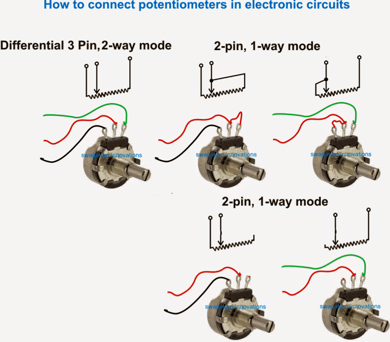
Keep that in mind, and have a look at the following three examples on how to wire a potentiometer. This is because it essentially is a resistor which has the ability to vary its resistance. Construction of ac servo motor. Switch • integral spring return returns motor to normal position in the event of power. Troubleshooting mounted speed control dial.

Source: surtrtech.com
Potentiometers located in the wiring compartment. Adjust motor speed to verify the proper motor speed controller functionality. Learn how to use potentiometer to control servo motor. Keep that in mind, and have a look at the following three examples on how to wire a potentiometer. Wiring diagram based on the control option desired.

Source: 14core.com
Connect the circuit as shown in figure i. Esp32 dev module) and com port. Copy the above code and paste it to arduino ide. Wiring these potentiometers (also known as pots for short) is fairly straightforward if you follow this diagram. To use external speed control turn integral potentiometer fully clockwise (100%).

Source: 2020cadillac.com
Servo motor wiring diagram zm056 series solid od 56mm servo motor encode slip ring drawing. Switch • integral spring return returns motor to normal position in the event of power. Arduino servo motor control using potentiometer push button save and play in 2021 arduino control circuit diagram. Wiring these potentiometers (also known as pots for short) is fairly straightforward if.

Source: growamis.com
Keep that in mind, and have a look at the following three examples on how to wire a potentiometer. Use of voltmeter over ammeter to verify a continuous circuit. A potentiometer is usually used to control an input signal so that it can be regulated. How to wire a potentiometer. Potentiometer diagram the potentiometer has two symbols, one of them.

Source: pinterest.co.kr
To use external speed control turn integral potentiometer fully clockwise (100%). Troubleshooting mounted speed control dial 1. The resistance at the both ends of the potentiometer is fixed, while the resistance of the middle pin can be changed by either. Esp32 dev module) and com port. To use external speed control turn integral potentiometer fully clockwise (100%).