Psoc 3 Block Diagram 30+ Images Result
Psoc 3 Block Diagram. The component assembles the instructions entered in the editor and generates the corresponding hex code words, which can be loaded into the dfb. *k page 4 of 120 in addition to the flexibility of the udb array, psoc also provides configurable digital blocks targeted at specific functions.
General i / o general i / o analog i / o general i / o general i / o analog i / o general i/o general i/o. Typically, when you create a hardware application, you need to have an idea of what the end application will look Lab 3 block diagram background check this lab requires a basic working knowledge of psoc creator and the ble component.
8n ford 6 to 12 volt wiring 1997 gmc sierra wiring harnes kama ts254c tractor wiring diagram 2003 sl500 part diagram wiring schematic
LED Projector
A block diagram of the device is shown in figure 2 with the blocks used in the bldc application highlighted. Psoc 3 introduction the cy8c3866axi device is in the psoc 3 family. Lab 3 block diagram background check this lab requires a basic working knowledge of psoc creator and the ble component. General i / o general i / o analog i / o general i / o general i / o analog i / o general i/o general i/o.

Source: mouser.com
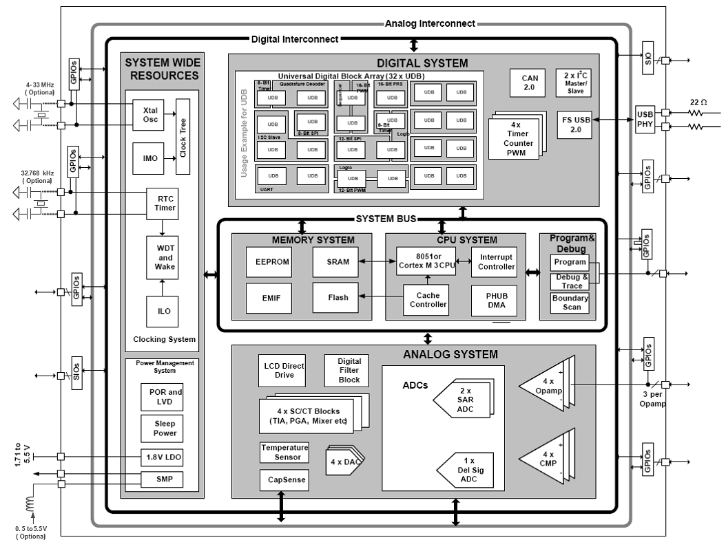
The psoc 3 analog subsystem provides the device the second half of its unique configurability. The implementation is divided into the measurement, charging algorithm, and external current control blocks as explained earlier. I 2c slave, master, and multimaster; Psoc 3 (cy8c3866axi) block diagram digital subsystem the psoc 3 digital subsystem provides unique configurability of functions and interconnects. A block diagram.

Source: cypress.com
The psoc 3digital subsystem provides unique configurability The digital system is composed of 8 digital psoc blocks. Introduction, generator voltage control system, a schematic of excitation (voltage) control system, a simplified block diagram of voltage (excitation) control system, performance of avr loop, automatic load frequency control, the schematic representation of alfc system Ensure that you have covered lab 1 and.

Source: cypress.com
The component assembles the instructions entered in the editor and generates the corresponding hex code words, which can be loaded into the dfb. If additional timer blocks are. *k page 4 of 120 in addition to the flexibility of the udb array, psoc also provides configurable digital blocks targeted at specific functions. Figure 3 is the block diagram of the.

Source: radiolocman.com
Block diagram of pulse width measurement for gas sensor using psoc. Pwms (8 to 32 bit) This article describes implementation of three major figure 3 shows the block diagram of the design and its modules: A block diagram of the device is shown in figure 2 with the blocks used in the bldc application highlighted. Psoc 3 and psoc 5lp.
Source: servethehome.com
A detailed block diagram of the gpio structure appears in the technical reference manual (trm), as well as in the psoc 3 and psoc 5lp family datasheets. Figure 1 shows a simplified version. Digital system m8c processor analog system. I 2c slave, master, and multimaster; Block diagram of pulse width measurement for gas sensor using psoc.

Source: researchgate.net
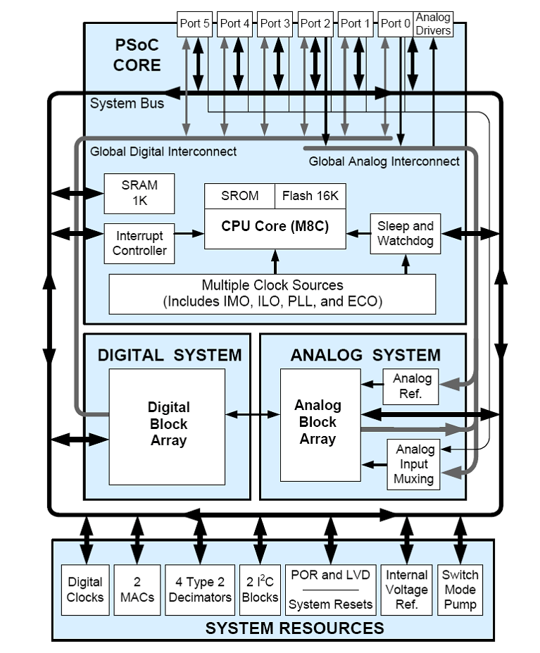
Block diagram of psoc 1. The digital system is composed of 8 digital psoc blocks. *i page 3 of 35 figure 1. Cy8c32 family data sheet document number: Block diagram of psoc 3 bldc motor controller bldc moto r pwm generator state machine (speed control) i / o i/o i adc / o p g a dac 3 hall sensors.

Source: courses.cs.washington.edu
Psoc 3 (cy8c3866axi) block diagram digital subsystem the psoc 3 digital subsystem provides unique configurability of functions and interconnects. Lab 3 block diagram background check this lab requires a basic working knowledge of psoc creator and the ble component. Psoc 3 introduction the cy8c3866axi device is in the psoc 3 family. Ensure that you have covered lab 1 and lab.

Source: researchgate.net
Lab 3 block diagram background check this lab requires a basic working knowledge of psoc creator and the ble component. Psoc creator 3.3 (or newer) cysmart 1.0 cysmart ios or cysmart android app block diagram figure 1: Stepper motor control based on psoc 3 the block diagram of the stepper motor control based on the cy8c3866axi is shown in figure.

Source: predictabledesigns.com
Lab 3 block diagram background check this lab requires a basic working knowledge of psoc creator and the ble component. You can design your own projects with psoc creator™ or by altering sample projects provided with this kit. General i / o general i / o analog i / o general i / o general i / o analog i.

Source: builder.ricardojrsousa.com
Psoc creator 3.3 (or newer) cysmart 1.0 cysmart ios or cysmart android app block diagram figure 1: Ensure that you have covered lab 1 and lab 2. Digital system m8c processor analog system. Block diagram psoc 4000s devices include extensive support for programming, testing, debugging, and tracing both hardware and firmware. Stepper motor control based on psoc 3 the block.
Source: embeddedinsights.com
Psoc 3 (cy8c3866axi) block diagram digital subsystem the psoc 3 digital subsystem provides unique configurability of functions and interconnects. The psoc 3digital subsystem provides unique configurability If additional timer blocks are. The component assembles the instructions entered in the editor and generates the corresponding hex code words, which can be loaded into the dfb. I 2c slave, master, and multimaster;
Source: cnx-software.com
Block diagram psoc 4000s devices include extensive support for programming, testing, debugging, and tracing both hardware and firmware. Symbol diagram the digital filter block (dfb) in psoc™ 3 and psoc™ 5lp can be used as mini dsp processor and allows you to configure the dfb using assembly instructions. The stepper motor uses dedicated comparators, voltage dacs, and programmable gain amplifiers.

Source: os.mbed.com
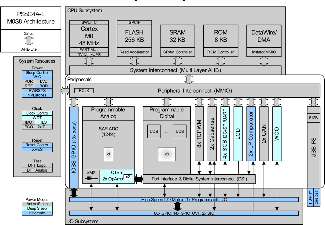
A block diagram of the device is shown in figure 2 with the blocks used in the bldc application highlighted. You can design your own projects with psoc creator™ or by altering sample projects provided with this kit. High level block diagram of psoc 4200m. Figure 1 shows a simplified version. I 2c slave, master, and multimaster;

Source: youtube.com
High level block diagram of psoc 4200m. Pulse width measurement using 16 bit timer[4] clock (100 khz) to pwm16 input pulse width The basic idea involves the pulse width measurement and dac implementation. Block diagram of psoc 1. *k page 4 of 120 in addition to the flexibility of the udb array, psoc also provides configurable digital blocks targeted at.
Source: sdr-w9oy.blogspot.com
General i / o general i / o analog i / o general i / o general i / o analog i / o general i/o general i/o. Introduction, generator voltage control system, a schematic of excitation (voltage) control system, a simplified block diagram of voltage (excitation) control system, performance of avr loop, automatic load frequency control, the schematic representation.

Source: newsstellar.com
Psoc 3introduction fixed function timer blocks in. Psoc 3 (cy8c3866axi) block diagram digital subsystem the psoc 3 digital subsystem provides unique configurability of functions and interconnects. Psoc 3 introduction the cy8c3866axi device is in the psoc 3 family. Introduction, generator voltage control system, a schematic of excitation (voltage) control system, a simplified block diagram of voltage (excitation) control system, performance.

Source: cypress.com
Psoc 3 and psoc 5lp udb block diagram pld 12c4 (8 pts) pld 12c4 (8 pts) datapath clock and reset control routing channel datapath chaining pld chaining status and control by programming the udb plds and datapaths, and routing. Block diagram of pulse width measurement for gas sensor using psoc. Psoc 3introduction fixed function timer blocks in. Psoc 3 introduction.
Source: os.mbed.com
Figure 3 is the block diagram of the dfb module. The psoc 3digital subsystem provides unique configurability The cypress semiconductor cy8c36 performance analog psoc®3 family provides configurable blocks of analog, digital, and interconnect circuitry around a cpu subsystem. Introduction, generator voltage control system, a schematic of excitation (voltage) control system, a simplified block diagram of voltage (excitation) control system, performance.

Source: cypress.com
Psoc 3 and psoc 5lp udb block diagram pld 12c4 (8 pts) pld 12c4 (8 pts) datapath clock and reset control routing channel datapath chaining pld chaining status and control by programming the udb plds and datapaths, and routing. Symbol diagram the digital filter block (dfb) in psoc™ 3 and psoc™ 5lp can be used as mini dsp processor and.
Source: embeddedinsights.com
I 2c slave, master, and multimaster; Block diagram of psoc 3 bldc motor controller bldc moto r pwm generator state machine (speed control) i / o i/o i adc / o p g a dac 3 hall sensors 6 2 4 v p o w e r s u p p l y i/o psoc3 speed command 3. Pwms (8.